VariCAD
VariCAD
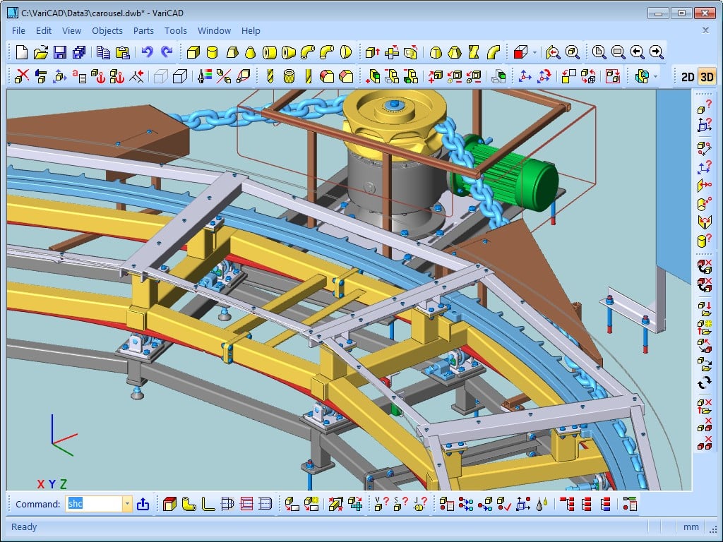
O VariCAD é um sistema de CAD 3D/2D, vocacionado especialmente para o desenho de engenharia mecânica. Permite aos engenheiros, criar, avaliar e modificar os seus modelos de uma forma muito rápida, e é vendido num único pacote “completamente carregado”, com todas as funções.
O VariCAD fornece uma excelente relação preço-performance, tornando-o, uma das escolhas mais inteligentes do mercado. O Interface Gráfico Utilizador do VariCAD (GUI), foi criado para permitir uma orientação rápida e intuitiva, em ambos 3D/2D.
A interface reflete o processo de pensamento de um engenheiro, de modo a que as ideias possam ser capturadas e comunicadas, com o mínimo de passos possíveis. Todos os comandos foram criados com atenção à facilidade.
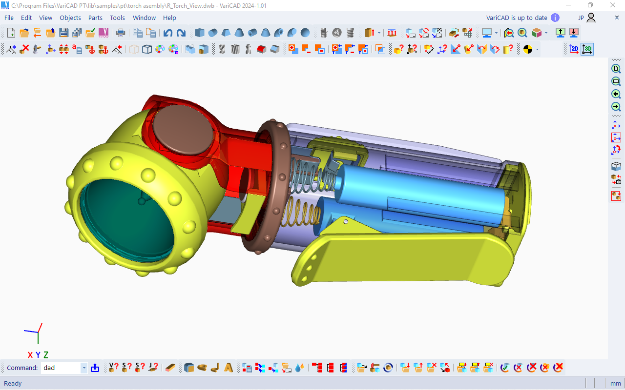
Existe um cursor inteligente, vários modos de detecção e seleção, linhas de construção 2D e uma grelha ortogonal. Estas são apenas algumas das ferramentas, que permitem trabalhar com o VariCAD de modo muito fácil. Pode iniciar criando um modelo 3D e depois usá-lo para criar ficheiros de desenho automaticamente, com vistas, ou então desenhar simplesmente no 2D. Desenhar no 3D, é geralmente mais “natural,” porque é menos ambíguo e representa de modo mais fiel, quer as peças ou as montagens.
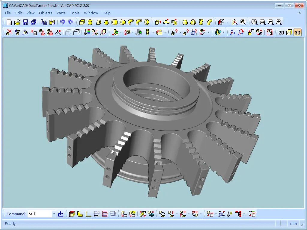
Os modelos criados no 3D, são mais facilmente convertidos para documentação 2D convencional. O VariCAD fornece uma biblioteca de sólidos básicos 3D (prisma, cilindro, cone, etc.), que podem ser facilmente modificados pela edição dos seus perfis originais ou dos seus parâmetros. Os sólidos, também podem ser facilmente criados, pela rotação de perfis, extrusão ou evolução entre perfis.
Para ferramentas mais complexas, incluindo rotações de combinação entre dois perfis, evoluções entre um círculo e um retângulo e criação de superfícies helicoidais, também existem funções disponíveis. Os sólidos podem ser adicionados ou subtraídos, representando deste modo árvores Booleanas de peças mecânicas reais. Temos também operações pré-definidas, como furos, faces, abertura de escatéis, ou aplicação de chanfros e/ou boleados.
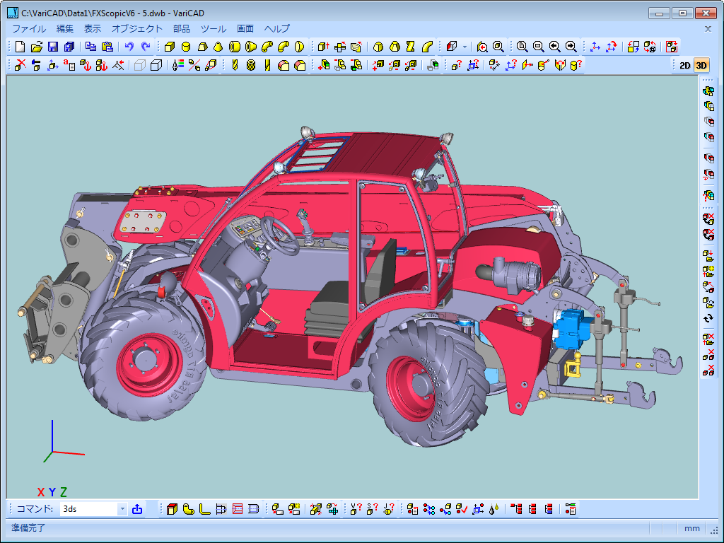
O VariCAD também fornece ferramentas para montagens. Se a ligação entre uma peça e uma montagem, estiver definida, quaisquer alterações realizadas no ficheiro peça, são refletidas no ficheiro de montagem e vice-versa.
Podem também ser definidas cópias ligadas. Neste caso, a edição de um objeto, causa a atualização de todas as cópias ligadas, em caso de alteração. Temos ainda grupos de sólidos, para tornar a seleção e a visibilidade mais simples.
Uma das excelentes funcionalidades da modelação 3D, é a verificação e o controle de colisões entre componentes. O VariCAD pode controlar as montagens 3D, para possíveis colisões (volumes sobrepostos) entre componentes. O VariCAD pode calcular áreas de superfície, volumes, massa, centros de gravidade e momentos de inércia. Está também incluída uma biblioteca de cálculos mecânicos, para peças standard, usadas diariamente pelos engenheiros mecânicos.
Estes cálculos incluem, molas à tração e compressão, ligações aparafusadas pré-tensionadas, cavilhas e chavetas, rolamentos, barras e vigas sob tensões combinadas (torsão e flexão), rodas dentadas de diversos tipos e correias.
VariCAD contém bibliotecas de peças mecânicas standard (ANSI, DIN), tais como parafusos, porcas, cavilhas, freios, chavetas, anilhas, rolamentos e perfis normalizados. Possui também opções para símbolos de hidráulica, pneumática e eletricidade. Os modelos 3D, são facilmente convertidos para desenhos 2D, de modo a produzir documentação de desenho. É possível criar vistas 2D de um ou mais sólidos selecionados, definindo as vistas no 3D. Como complemento, é possível exportar secções especificadas.
O VariCAD pode também criar superfícies planificadas (planas) a partir dos sólidos 3D. As coordenadas XY das superfícies planificadas, podem ser guardadas para um ficheiro de texto, de modo a serem tratadas posteriormente. É possível também introduzir coeficientes de torsão, de modo a configurar os seus cálculos.
Podemos desenhar em milímetros ou em polegadas. O VariCAD fornece ferramentas para manter as bases de dados de desenho, que representam a estrutura de dados do produto. Estas podem ser criadas manualmente (usando a extração a partir da montagem), ou através do carregamento de um ficheiro.
Existem constrangimentos entre os dados de uma peça e as legendas de um desenho de montagem, com a base de dados de montagem. É possível construir uma lista de materiais (BOM) a partir da base de dados e depois modifica-la facilmente através do uso de comandos, como a alteração dos atributos de massa, ordenamento de informações. A estrutura de dados do produto (BOM) pode ser exportada para outros sistemas ou ainda para uma folha de cálculo. A criação automática da lista de materiais e da legenda, é outra das funcionalidades muito úteis do VariCAD.
O VariCAD pode trocar ficheiros com outros sistemas de CAD. É possível exportar ficheiros em formato STEP (3D), STL (3D), IGES (3D), DWG (2D), DXF (2D) e importar em STEP (3D), DWG (2D), DXF (2D). Os ficheiros podem ser convertidos individualmente ou em rotina batch, deste modo convertendo vários ficheiros num único passo.
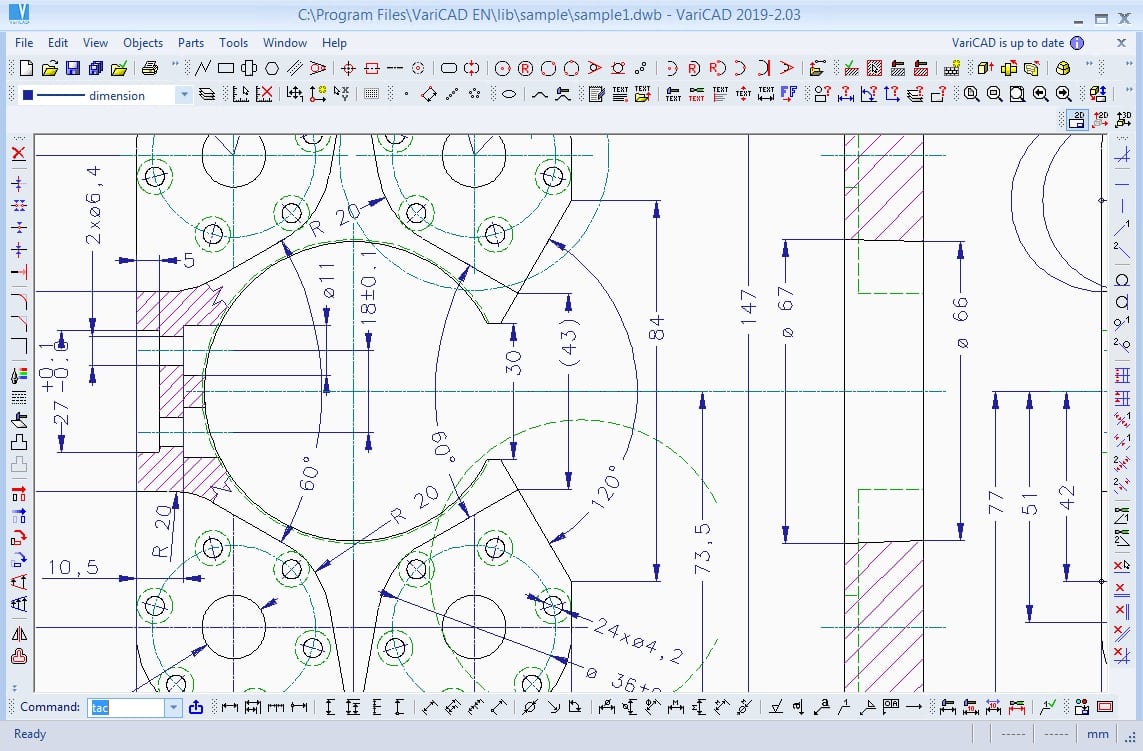
O VariCAD suporta ainda as atualizações de um desenho 2D, depois de existirem alterações no 3D. As funções de desenho são orientadas para o uso fácil em engenharia. Algumas das funções de desenho 2D, incluem:
- Cursor inteligente com deteção automática de objetos;
- Vários modos de ganchos;
- Linhas de construção auxiliares;
- Modo ortho;
- Grelha rectangular;
- Níveis de desenho (layers);
- Até 250 níveis;
- Criação de blocos;
- Padrões com reconhecimento e detecção de fronteiras;
- Símbolos de acabamento superficial de superfícies;
- Símbolos de soldadura;
- Símbolos de tolerâncias e mais…

VariCAD
VariCAD is 3D / 2D CAD software primarily intended for mechanical engineering design. The comprehensive CAD software enables designers to quickly create, evaluate, and modify their models. The software is sold as one “fully loaded” package, with all features and functions, for one very affordable price.
VariCAD delivers an excellent performance-to-price ratio, making it one of the smartest choices on the market today. VariCAD’s Graphical User Interface (GUI) has been designed to allow quick and intuitive 3D/2D orientation.
It has been carefully tailored and tuned to reflect the thought process of a designer, so that ideas can be captured and communicated with a minimal number of steps. All commands were created with a focus on ease of use.
You can start by creating a 3D model and then use it to automatically create drawings files, or you can draw only in 2D. Designing in 3D is generally more “natural,” in that it closely represents actual parts and assemblies. Models created in 3D are easily converted into conventional 2D documentation. VariCAD provides a library of basic 3D shapes (like a box, cylinder, cone, etc.), which are easily modified by editing their dimensions. Solids can be created also by profile rotation, extrusion, or lofting. More complex tools include rotation blending between two profiles, lofting between a circle and rectangle or between different profiles, and creation of helical surfaces.
Solids can be added or subtracted, thus forming Boolean trees representing real mechanical parts. Boolean operations have options of automatic trimming (so called selective Boolean operations). Predefined operations like drilling of holes, face milling or groove milling are also available. Edges can be rounded or chamfered. VariCAD provides a lot of possibilities of solid transformations or their editing. Also, you can easily edit Boolean trees – either selecting solid parts from 3D, or selecting them from a list displaying structure.
VariCAD also provides tools for assembly support. If the link between a part and assembly is defined, any changes made to the part file are reflected in the assembly file and vice-versa. Linked copies of solids can also be defined (so called identical solids). In such case, editing of one object causes update of all its identical copies. Solid groups can be defined as well, making selection and visibility changes simple, for multiple objects. One excellent feature of 3D modeling is component interference checking.
VariCAD can check 3D assemblies for possible collisions (overlapping volume) between components. VariCAD can calculate 2D section area, surface area, volume, mass, center of gravity, and moment of inertia. Mechanical parts calculations are also included – for standard parts used every day by mechanical designers. There are calculations of tension and compression springs, pre-stressed bolted connections, pins and parallel keys, grooved shafts, bearings, beams under combined stress (bending and torsion), spur and bevel gearing geometry, and belt drives.
VariCAD can also create developed (unbent) surfaces of 3D solids or sheet metal parts. The XY coordinates of developed surfaces can be saved into a text file for further processing. You can input bending coefficients in order to customize your calculations, to reflect material and technology.
VariCAD contains libraries of standard mechanical parts (ANSI, DIN), such as bolts, nuts, pins, plugs, cotters, gaskets, bearings, rolled and drawn shapes, and hydraulic, pneumatic, and electrical symbols. 3D models are easily converted into 2D drawings to produce conventional drafting documentation. You can create 2D views of one or more selected solids by defining the views in 3D. In addition, you can also export specified sections.
You can draw in millimeters or in inches. VariCAD provides tools for maintaining the data structure of the product. There are links between attributes of parts and content of title blocks. You can create a bill of material (BOM) from an assembly, or easily modify the database using commands like mass attribute changes, sorting of information, etc.
Each part can contain attributes, like name, type of material or supplier. Such data can be used for material requisitions, creation of bills of materials (BOM), filling of title blocks, or other purposes. The data structure of the product (BOM) can be exported into other systems or into a spreadsheet. A mask is used for BOM customization; you can modify it exactly according to your needs. Mask defines usage of solid or assembly attributes, working with title blocks, methods of data exports from BOM etc.
VariCAD can interchange files with other CAD systems. You can export STEP (3D), STL (3D), IGES (3D), DWG (2D), DXF (2D) files, and import STEP (3D), DWG (2D), DXF (2D). The files can be converted individually or in batch routines, thereby converting multiple files in one step.
VariCAD supports updates of a 2D drawing after changes in 3D. Drawing functions are optimized for easy use in engineering. Some handy features of 2D drawing include:
- Automatic detection of objects and snap points;
- Numerous snap modes;
- Auxiliary construction lines;
- Ortho mode;
- Rectangular grid;
- Drawing layers;
- Block creation;
- Hatching with automatic border detection;
- Advanced dimensioning;
- Finish symbols;
- Welding symbols;
- Tolerance symbols, and many more.